
Overhauling the Running Gear on an Iconic Fort Lauderdale Riverboat Attraction
 If you live in or have visited the Greater Fort Lauderdale area, chances are pretty good that you have booked a cruise on the Jungle Queen Riverboat or at the very least seen her plying the New River. First launched in 1935, Jungle Queen Riverboat cruises have been delivering a laid-back, casual cruising experience to its customers for more than 80 years.
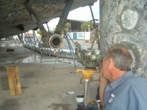
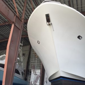
The “old fashion sternwheeler” was recently hauled at LMC and our team of running gear mechanics was called upon to overhaul her running gear from shafts to seals, props and rudders as part of routine maintenance.
After performing a full running gear inspection, we pulled the shafts, props and dropped the rudders. We also installed and aligned a new babbit bearing on her shaft. Babbit bearings are known for their resistance to galling and are often used in the marine applications for vessels of this type. As part of the overhaul, we will also remove and re-install the shaft and shaft muff couplings, supply a new Tides Marine shaft seal system and four new cutless bearings.
Our in-house machine shop, Straight Line Marine, will straighten both the port and starboard main shafts as well as the tailshafts. We will then lap the props back on the shafts as well as fit, face and lap the port and starboard couplers.
Work on the rudders required us to disconnect the tie bar and tiller arms. Once the rudders were out of the vessel, we replaced the rudder packing and stuffing box hardware. Our final step will be to do a full engine alignment to ensure smooth, vibration-free cruising.
Once the work is complete and the old gal is launched again, she will be ready to delight visitors to and residents of “the Venice of America” for years to come.
Upgrading the Wartsila Shaft Seal System as Part of a Running Gear Overhaul
Optical Scope Alignment check for accuracy
When a 126’ Oceanco Motor Yacht was hauled at LMC, we were hired to perform an extensive overhaul on the vessel’s running gear. Since it had been a while since the running gear was inspected, we first performed a laser deck target before she was pulled out of the water. This is a necessary step in order to ensure that the vessel is blocked correctly for future alignment work.
As part of the overhaul, we removed the shafts, props, stern tube and dropped the rudders. This particular yacht had an older Wartsila EL shaft seal system which was difficult and expensive to maintain. For this reason, we upgraded the shaft seal system to a Wartsila PSE model. Because of space constraints and the different dimension of the two systems, we needed to work with a local aluminum welding contractor to modify the stern tubes in order to accommodate the new shaft seal system. These seals also need to be installed on the centerline of the shafts so we performed an optical scope alignment from the main struts and transmission to the stern tube to ensure exact placement.
Because of excessive wear on the main strut Thordon bearings, we removed the bearings so our in-house machine shop, Straight Line Marine, could cleaned them up before re-installing back into the vessel. Our machine shop also straightened the shafts, lapped the propellers and fit, faced & lapped the port and starboard couplers.
Once all the prep work was completed, we re-installed the propellers and propeller shafts along with the rudders, aligned the engines and performed a final laser deck targeting procedure to ensure that the vessel would not experience any vibrations under way.
Upgrading a Wartsila shaft seal system takes an experienced team, the right tools and precise coordination with outside contractors to make sure the job is done right.
When Time is of the Essence, High Seas Delivers Results
 While at the Fort Lauderdale International Boat Show, we were approached by the Captain of a new 164’ yacht whose vessel was on display at the show. After a brief sea trial before the show, the vessel had reason to believe that the shafts were bent and Thordon bearings were damaged. While this was an unfortunate turn of events, the problem was magnified by the fact that the yacht was scheduled for a charter in the Caribbean only a week and a half after the show ended.
As you can imagine, most of the boat yards in South Florida were booked for the days following the boat show leaving this Captain with little options of getting the work done quickly. And forgoing the work for a long trip south was not an option. Get it done or cancel charters. We worked with Lauderdale Marine Center to “squeeze” the yacht into the haul out schedule a couple of days after the show ended.
Once hauled, our team sprang into action. While still in the blocking process, the High Seas team started pulling the props. The next day the shafts were out of the vessel and on the way to the machine shop. Fortunately, our machine shop, Straight Line Marine, is located on site at Lauderdale Marine Center. No loss of time calling for a truck to load and transport to an outside facility. Within a short period of time, the machine shop went to work on straightening. With a little overtime, the shafts were ready to install a day later.
We also found Thordon bearings that were damaged and needed to be replaced. Since this was suspected during our first meeting at the boat show, we ordered Thordon material and it was on-hand before the vessel hauled. Thordon bearings require custom machining to fit the vessel. Our machine shop got it done while the shafts were being straightened.
We then re-installed the shafts and props, did an optical scope alignment and sea trial and sent the yacht on her way in a matter of days so she could make her charter.
This Captain found himself in a tight spot but working with Lauderdale Marine Center to fit this 164-footer into the schedule, hard work on the part of the High Seas and Straight Line Marine teams, a machine shop on-site and ready to go and the dedication to customer service that is the foundation of our company, this yacht is on her way to making a charter guests’ dream vacation come true.
Fort Lauderdale International Boat Show is Right Around the Corner.
![]() And we will be there with Lauderdale Marine Center in Booth #640. Stop by and visit with us, November 1-5 at the Bahia Mar Yachting Center. We will have our experienced technicians and mechanics in the booth from both High Seas Hydraulics and High Seas Yacht Service to answer any questions you may have on running gear or hydraulic systems. Hope to see you at the Show!
And we will be there with Lauderdale Marine Center in Booth #640. Stop by and visit with us, November 1-5 at the Bahia Mar Yachting Center. We will have our experienced technicians and mechanics in the booth from both High Seas Hydraulics and High Seas Yacht Service to answer any questions you may have on running gear or hydraulic systems. Hope to see you at the Show!
Re-powering the World’s Largest Sport Fishing Boats
Optical Scope Alignment check for accuracy
We recently had the opportunity to work on the world’s largest sport fishing boat, a 144’ Trinity. The yacht was recently sold and her new owner had her hauled at Lauderdale Marine Center for a complete refit including new engines (repower). The vessel originally had old Paxman engines that were removed by cutting a large hole in the side of the boat and replaced with new MTU engines.
A job of this size requires precision coordination with other contractors at LMC who handle engine rigging and removal, welding, plumbing, painting and full MTU service commissioning.
For our part, we first performed a laser deck targeting procedure to block the vessel properly for hull work and future alignments. We then removed the running gear from the boat so our machine shop could straighten the shafts, lap fit face couplers and propellers and ABS crack test the shafts.
Next, we performed an optical scope alignment of the remote transmissions to the shaft line and used Chockfast® to hold the transmissions in place. Working closely with the aluminum fabricators and MTU engine plans, our team made sure that the new engine beds and stringers were in the right position and the right height for the new engines and engine mounts. The next step was to install the new engine mounts on the engines and rough align the engines with the transmissions using lasers for final engine room fabrication.
Our machine shop, Straight Line Marine, then machined the new sole plates for the engine mounts. We also installed Gieslinger torsional couplings between the engines and transmissions and provided all new bearings and shaft seals.
Once the vessel was launched, we did a final laser alignment of the engines to the transmissions and used Chockfast to place all engine mounts into position.
The vessel is now ready to take her owners far and wide in search of big game fish.
Strut Alignment using Cardan Shafts
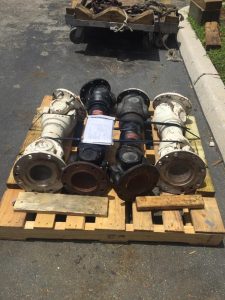 As discussed in a previous post, we were commissioned to perform a strut alignment on a 120’ Ferretti after she ran aground. This vessel had cardan shafts. Marine cardan shafts, while fundamentally the same as u-joint shafts in cars and trucks, are unique because of the large flanges they have for higher horse power capabilities. They are commonly used with remote transmissions where the transmission (gearbox) are separate from the main engine.
Once we removed the cardan shafts from the boat, we sent them to a company in the Mid-West where they inspected and replaced where needed the needle bearings in the universal joints (U-joint) and balanced the shafts. Balancing cardan shafts takes a highly-specialized piece of equipment.
It is very important to balance the cardan shaft to eliminate the possibility of torsional vibrations. Torsional vibrations are caused by two things: the u-joint operating angle at the “drive” end of the drive shaft and the orientation (phasing) of the yokes at each end of the drive shaft. A torsional vibration is a twice per revolution vibration. It will cause the drive shaft, “downstream” of the front U-joint, to “speed up” and “slow down” twice per revolution. That means that the engine producing a constant speed of 3,000 RPM can actually be attached to the drive shaft that is changing speed 6,000 times per minute. The amount of that change in speed, called the magnitude, or size of the change, is proportional to the size of the angle at the drive end of the drive shaft, or the amount of misalignment between the yokes at the drive and driven end of your drive shaft. Torsional vibrations are serious vibrations that can cause the shaft to bend and potentially break.
When a drive shaft is assembled, its inner components usually consist of a slip yoke on one end and a tube yoke on the other end, and they are usually assembled in relation to each other. This is called PHASING. Most drive shafts are assembled with their yokes in line, or “IN PHASE”. A drive shaft that is “in phase” and has the correct operating angles at the drive end of the shaft does not create a torsional vibration. Drive shafts that are NOT in phase will vibrate with the same twice per revolution vibration as a drive shaft with incorrect operating angles.
Understanding the intricacies of the various components found in many mega-yachts ensures that the job gets done and gets done right.
When a 120’ Ferretti was hauled at Lauderdale Marine Center, the captain hired us to perform shaft straightening in our machine shop, Straight Line Marine and a strut alignment on the yacht as a result of a recent grounding. The ship had significant vibration issues that needed to be addressed.
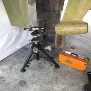 Once the struts were removed, cleaned and straightened, the re-installation began with prepping the surface to remount the struts. Upon completion, we used a forklift and ratchet straps to reinstall the struts in the boat. To ensure exact alignment, we used an optical scope. Optical Scope Alignments or “Scoping” for short; is the most advanced method for obtaining a perfect marine shaft alignment with struts, shaft logs, engines or v-drives. Scoping is the latest generation of alignment technology and far more advanced than the old piano wire system and even laser alignments. The Optical Scope Alignment allowed our mechanics to make exact adjustments to ensure that the struts were perfectly seated to the haul.
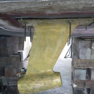
To finish the re-installation of the struts, we use CHOCKFAST® ORANGE to fill the gaps between the strut installation and the hull of the boat. CHOCKFAST is an engineered epoxy chocking material that is used to cast-in-place permanent machinery supports for all sizes and types of main engines and marine auxiliary equipment. Because it conforms precisely to any surface profile, CHOCKFAST eliminates the machining of foundation and mounting surfaces as well as the fitting of the old-style steel chocks.
CHOCKFAST® Orange is a conveniently pourable, two-component, structural epoxy “chock” that replaces tediously fitted steel shims (or steel chocks) assuring exact contact with machined or un-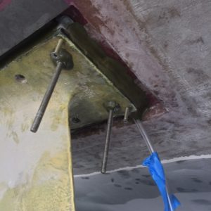 machined equipment bed plates. This is the only method to gain an accurate alignment without complicated line boring or other machining processes.
This yacht is now ready to get back on the open seas for new adventures and smooth sailing.
Need Running Gear and Hydraulic Work Done on your Yacht – Work with Us
A 106’ Westport yacht was recently hauled at Lauderdale Marine Center for a variety routine maintenance projects including shaft work, bearing replacements and an overhaul on several hydraulic systems. To streamline the process and help the captain and crew better manage the project, they contracted with both High Seas Yacht Service for the running gear portion and High Seas Hydraulics to handle the hydraulics work.
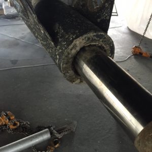 Our running gear mechanics inspected the shafts to ensure they were straight and aligned and replaced the bearings and seals. Normal wear and tear associated with running the vessel and prolonged exposure to salt water makes this task a necessary evil for properly maintaining the boat. As seen in the adjacent photo, there was a visible gap where the cutlass bearing adjoined to the shaft.
We were also commissioned to replace the seals on the lower stabilizer fins. ABT Trac, one of the more popular brands, recommends changing the 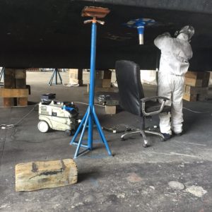 lower stabilizer fin seals every couple of years but at least every six years depending on use. The components on the stabilizer are constantly working except is absolute calm seas, so the wear and tear can be considerable. After dropping the fins, we proceeded to change out the old lower stabilizer fin seals with new ones, check the hoses and cylinders, then reassembling the units.
In addition to the routine maintenance on the stabilizer systems, we flushed the entire hydraulic system using the simple drain, filter, fill approach commonly referred to in our shop as a DFF. This type of flush is more of an “oil change” and is part of routine maintenance. It is not appropriate where a more serious condition such as water, metal particles or other contaminants are found in the oil. The process calls for draining the hydraulic tank, changing out the filters and refilling the tank with hydraulic fluid.
 To round out the work on this Westport, we did an overhaul on the bow thruster, single Maxwell windlass, the boat’s heat exchangers and the hydraulic steering system which was slow to respond.
From running gear to hydraulics, our teams at High Seas Yacht Service and High Seas Hydraulics, make easy work of maintaining the systems that make your vessel safe and operating smoothly.
Eliminating Engine Vibrations – Is a Strut Alignment the Answer?
We recently worked on a 96-foot Ferretti yacht that had run aground and was experiencing considerable engine vibrations. Our field technicians with High Seas Yacht Service inspected the boat and found that the shafts were bent and one of the struts was bent and out of alignment. After pulling the props and shafts, we sent the shafts off to our machine shop, Straight Line Marine for straightening. Once the shafts were back in true, we sent them back to the vessel for re-installation after performing a full strut alignment on the vessel.
 Strut alignment is often overlooked when trying to determine the cause of vibrations in a boat. All too often the first or second course of actions are shaft straightening or engine alignment when the root of the problem may lie in the struts. Struts can be out of alignment due to poor factory set-up or a hard grounding causing a bent or twisted strut.
Strut alignments are complex and require special tools and experienced mechanics. Once a strut is removed from the boat it is a major repair and should only be done by specialist in this field.
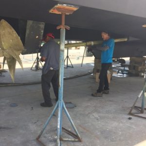
We begin the process with an optical scope alignment for precision measurements of the misalignment. In order to align the strut, it must be removed or dropped from the bottom of the boat. All strut bolts are removed and a considerable force is applied to break the bond between the strut and the hull. Proper equipment and safety are a major concern since some struts can weigh hundreds of pounds.
Once removed, the strut pad and hull pockets must be ground clean in preparation for installation. Extra jacking holes are drilled and tapped in the four corners of the strut pads to help with fine tuning adjustments. Once preparation is complete, the strut is hung back in its original place and the optical scope is once again used for precision alignment of the strut cutlass bearing.
When the strut is properly aligned, we use ChockFast to inject into the gap between the hull and strut to form a perfect fit with the bottom of the hull.
A strut alignment is typically a one-time project for any vessel unless it is driven hard aground. A properly aligned strut will free-up an engine to provide a smooth ride for comfort and higher speed with lower fuel consumption. For more details on performing a full strut alignment, click here.
When a 112-foot Westport yacht returned to Lauderdale Marine Center, our running gear team dropped in on the vessel for a courtesy visit and health check. The ship was in the yard last year and we did a full running gear job including shaft work and alignment.
Checking Tolerances
Since the yacht was back on the hard, our team checked the cutlass bearing clearance on the shafts to ensure that the shafts were properly aligned. The tool we used to perform this task is called a feelers gauge which are an assortment of fine thickened strips with marked thickness which are used to measure gap width or clearance between the shaft and the cutlass bearings. We also visually inspected the bearing seals.
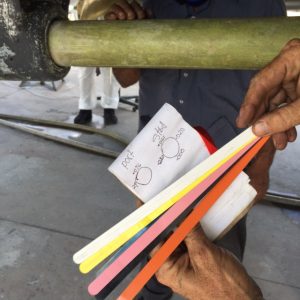
Feelers Gauge
We were happy to report back to the captain that everything checked out properly and the running gear work that we performed last year was holding true. When you engage High Seas Yacht Service, you can rest assured that we will stand by our work and go that extra mile to keep our valued customers sailing smoothly.
 Click to watch the video of a day at High Seas Yacht Service.
 Click to watch Marine Industries Association of South Florida video featuring Salty Jobs at High Seas Services.