
While performing routine maintenance on a 120 foot Bennetti yacht, we needed to pull the propeller shafts for inspection. Once the shafts were removed, we discovered that the Thordon plastic shaft bearings needed to be replaced.
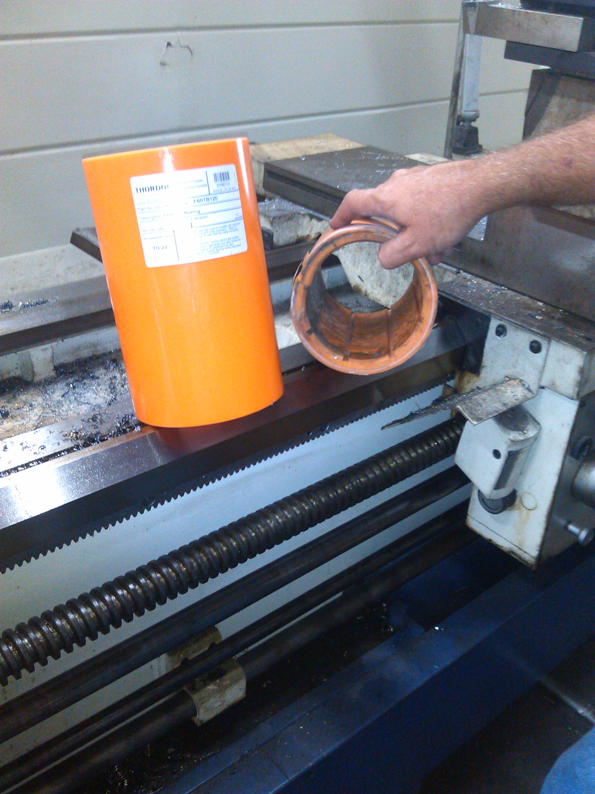
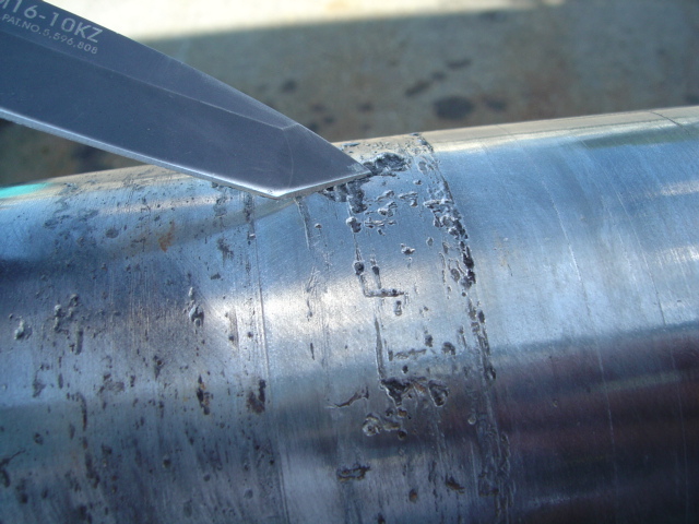
Worn Thordon bearing with new unfinished material
Thordon material is a hard compound that is an alternative to rubber cutless bearings. Thordon bearings are common in large commercial vessels (over 1,000 ton) and we see them in our yard on Trinity’s, Bennetti’s and other vessels from 120 foot and larger.
One advantage with Thordon bearings is the elimination of bearing squeal or, more technically, “stick-slip”. Bearing squeal is sometimes found with rubber bearings on stainless prop shafts when the shafts are turning extremely slowly. The shaft is not spinning fast enough to get the hydrodynamic lift of water between the rubber and the stainless steel. The result is a squealing sound.
Thordon bearings are custom machined to the vessel’s exact tolerances. The strut barrel or stern tube is measured by our machinist to 0.001” in many places. The shaft diameter must be measured as well. We then use a bearing calculator to get the exact inside and outside tolerances. Those tolerances are adjusted for an interference (liquid nitrogen) fit or a glue (epoxy) fit. They are also adjusted for the temperature of the machine shop at the time of the machining.
A great deal of care goes into the measurements and calculations. If the bearings are a few thousandths too tight on the shaft it will start an over heat condition that is a chain reaction and causes bearing failure. These bearings cannot be purchased off the shelf and should not come from a machine shop that did not come to the vessel to take careful measurements before machining.
Replacing the Oil Bath Shaft System – Part two
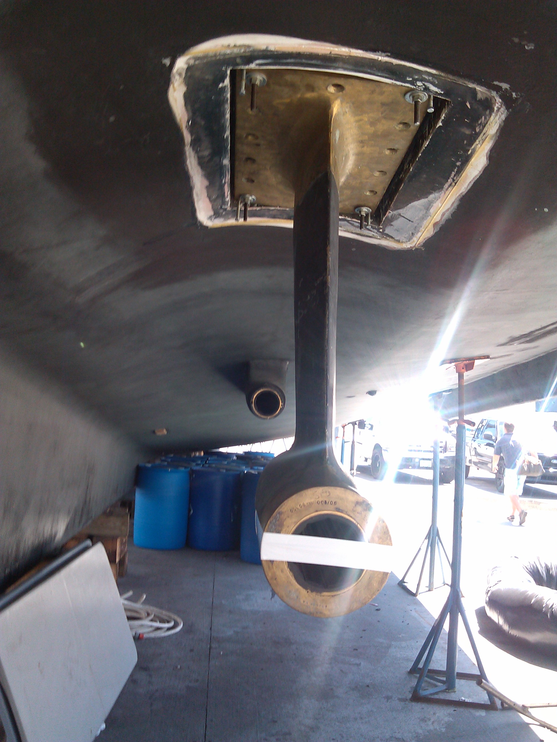
As we mentioned in our previous post, we are in the process of converting a 61 foot Blackwell “Carolina” Sportfish’s shaft system back to its original configuration from an Oil Bath Shaft System.
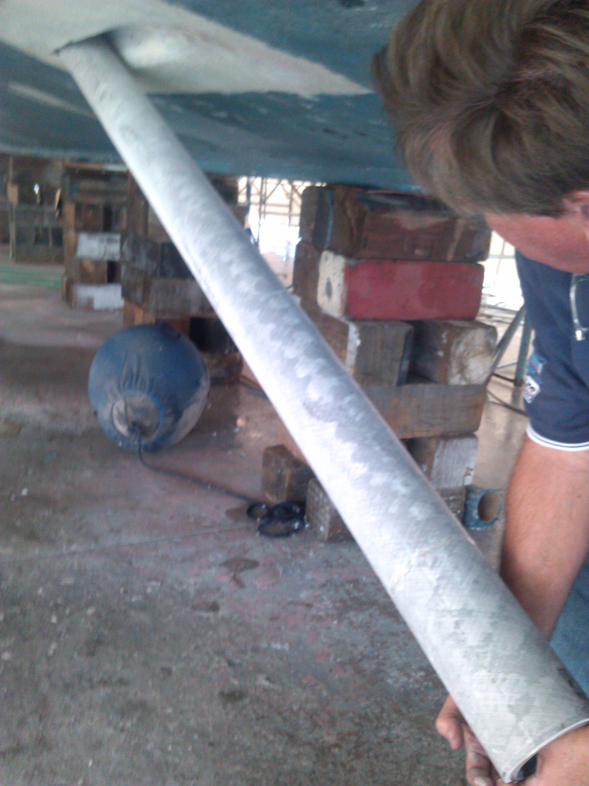
Sliding the new fiberglass stern tube into the hull prior to scoping
The Oil Bath Shaft system is an enclosed, oil lubricated, self-contained shaft and thrust bearing assembly which uses a stainless steel tube that is filled with oil. When we removed the Oil Bath Shaft system from the vessel, the stainless steel tube needed to come out. Once the stainless steel tube was removed, we installed a more traditional fiberglass stern tube. The key to this type of operation is the optical scope alignment. The tube had to be perfectly aligned since there is a cutless bearing at the aft end of the tube.
We use state-of-the-art optical scope technology, laser and reflective optic technology for precision alignments from strut to engine. Optical Scope Alignments or “Scoping” for short; is the most advanced method for obtaining a perfect marine shaft alignment with struts, shaft logs, engines or v-drives. Scoping is the latest generation of alignment technology and far more advanced than the old piano wire system and even laser alignments.
This process of installing a new fiberglass stern tube is not a common procedure and not many shops perform this type of work. Getting the perfect alignment is the most important step. When you work with a shop that has technicians specially trained in the use of the latest technology along with an innovative approach to problem solving, it helps ensure that the job is done right, every time.
 There is a 61 foot Blackwell “Carolina” fishing boat that is going through a major refit in our yard due to fire damage. During this time the owner wanted to return the vessel back to the original shafting arrangement. The vessel was repowered a few years ago and had an Oil Bath Shaft System installed which the owner wanted removed. This job required us to machine new shafts and couplers in our machine shop (Straight Line), order new stainless steel struts, new Veem propellers and a new Tides Marine shaft seal system. In addition to replacing the entire system, we also moved the engines back 8 inches in order to change the trim and stability of the yacht.

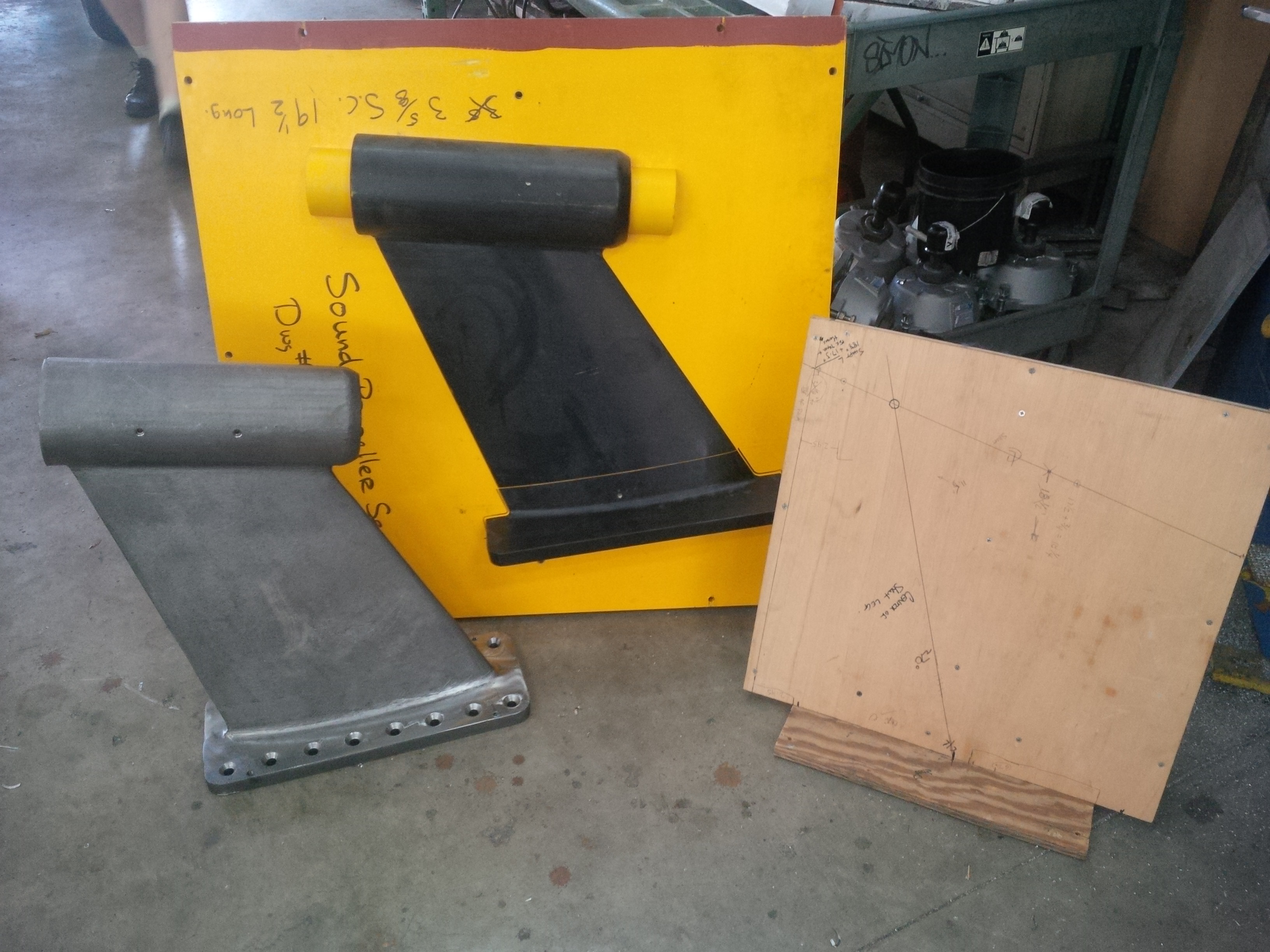
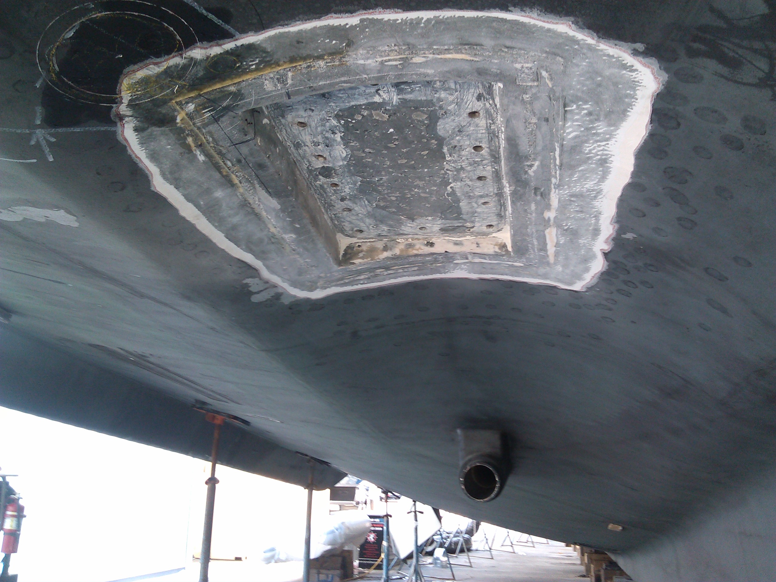
Comparing Naval Architect’s drawing with plywood mock-up
Since we were making a major change to the running gear we engaged a Naval Architect to redraw the running gear configuration, check all the shafting calculations and design new struts for the boat. The Naval Architect provided us with drawings and dimensions for the struts. However, that was based on limited detailed drawings of the vessel’s hull. From the design, we made a plywood mock-up of the new strut which we hung under the boat in order to refine the measurements. With the plywood in place we are able to set up the optical scope for a perfect alignment and find the exact location of the shaft centerline. Initial drawings from Naval Architects can be +/- .25 inches from the actual numbers needed for installation. Since the strut was molded and cast in stainless steel we needed to be absolutely sure the dimensions were accurate before placing an order with the foundry. Stay tuned for more articles as we align and assemble this vessel.
Improving the design and functionality of an older vessel.
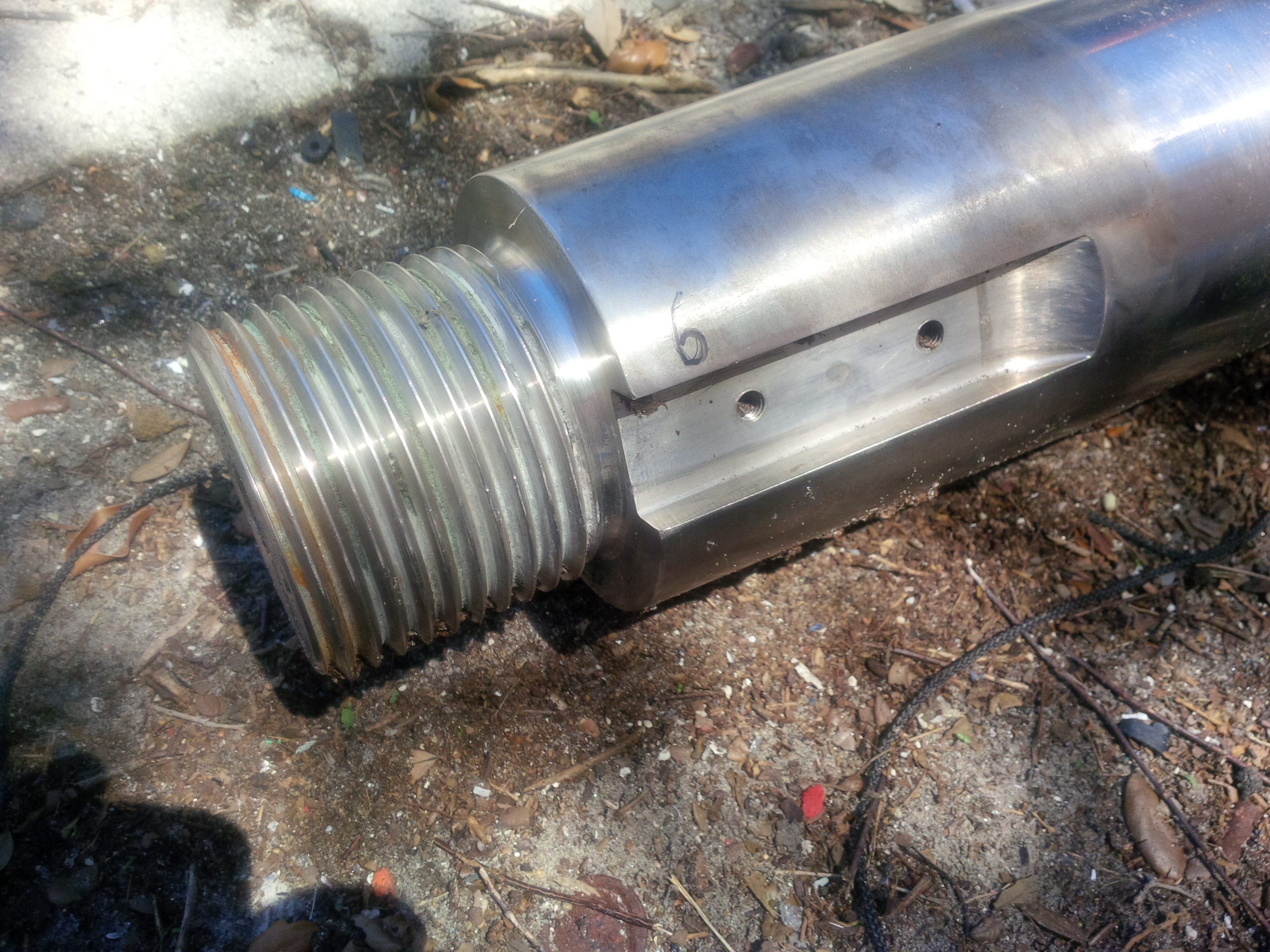
Old Shaft of the Yacht
While fabricating new 125mm (near 5 inch) shafts for a 1988 145 foot NQEA Lloyd’s Registered yacht, we had an opportunity to improve the design and functionality of the vessel.
The boat used a coupler nut attachment with one big nut on the coupler end in the engine room. The nut that was used would be similar to a propeller nut. Since the coupler nut is usually recessed into the coupler, it takes a very large socket to tighten or loosen it. In order to perform the work, we would have to make custom sockets that would fit on a 1” wrench and then, because of the amount of torque required, put a 3 foot long pipe on the wrench to get the leverage. Because this work is happening in the engine room between the engine and the shaft, we often find that do not have enough room to swing a long pipe or get the socket in place.
A more modern approach is the keeper plate or shaft locking plate. The end of the shaft
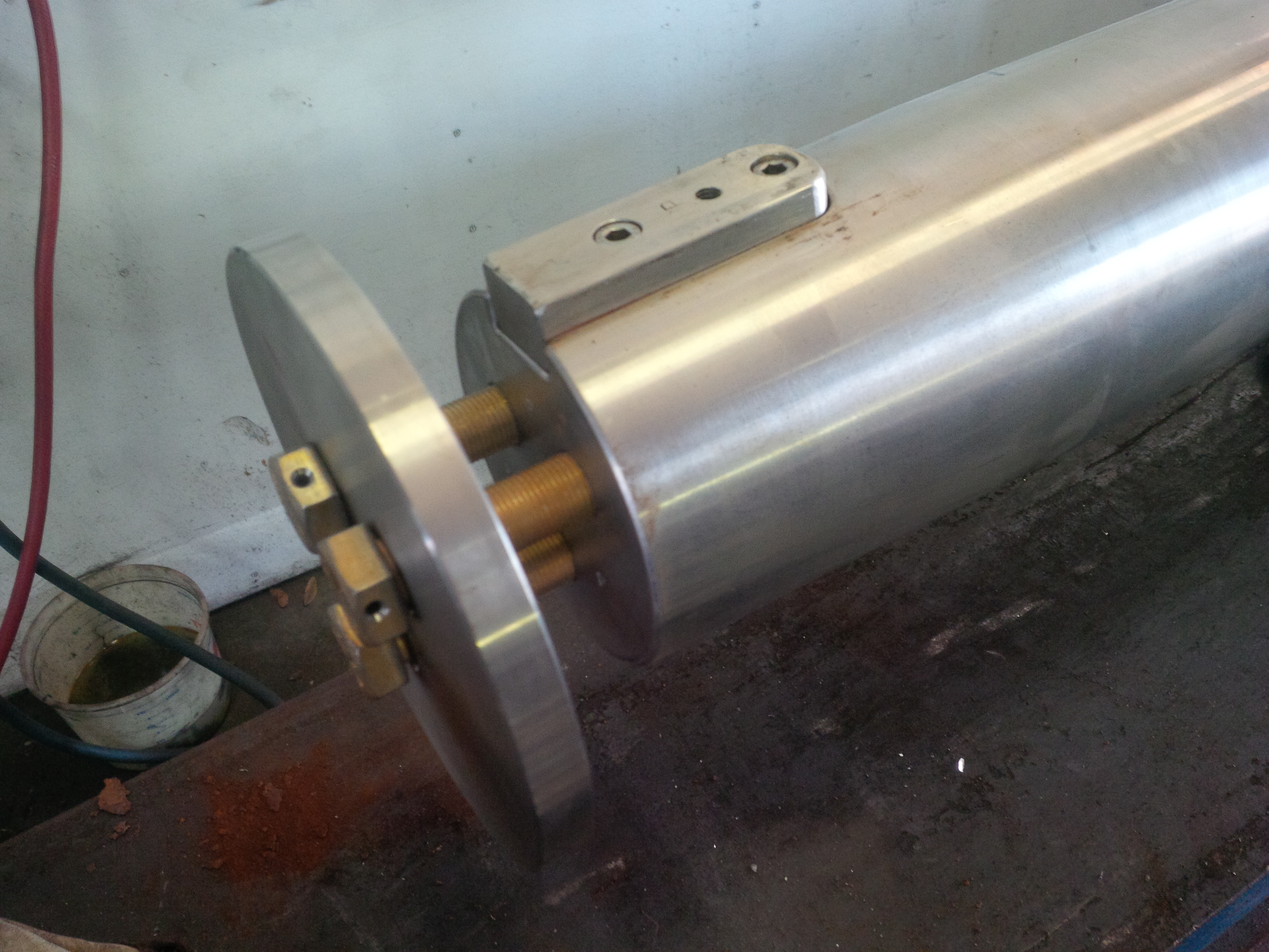
New couplet
is cut flush, drilled and tapped for much smaller bolts. Three ¾” hardened bolts are torqued down in a circle to draw the plate and coupler onto the shaft taper. A common ¾” socket can be used on a regular ½” or ¾” wrench. We no longer needed long cheater pipes since the torque required to draw up the plate is considerably less than that required on one big nut.
Since we were making new shafts, we wanted to take the opportunity to improve on this 1988 vessel. We used a naval architect to make the drawings and got everything approved by Lloyd’s surveyors in advance.
Building Lloyd’s Certified New Shafts
When working on Lloyd’s Register classification vessels, stringent rules apply to what can and can’t be done on certain aspects of the boats. More importantly, Machine Shops and their machinist must be properly certified to perform the work. Straight Line Marine, located at the Lauderdale Marine Center, holds all applicable certifications to work on these classes of boats. Straight Line Marine is a division of High Seas Yacht Service and along with the High Seas Hydraulics division, the three companies can perform a wide range of services all under one roof.
A 1988 145 foot NQEA, with six shafts and four SKF hydraulic muff couplers, needed two main shafts replaced because they were worn and pitted. The two main shafts were the final shafts that connect to the engine. Because this yacht is Lloyd’s classified, standard shaft cladding repairs were not an option.
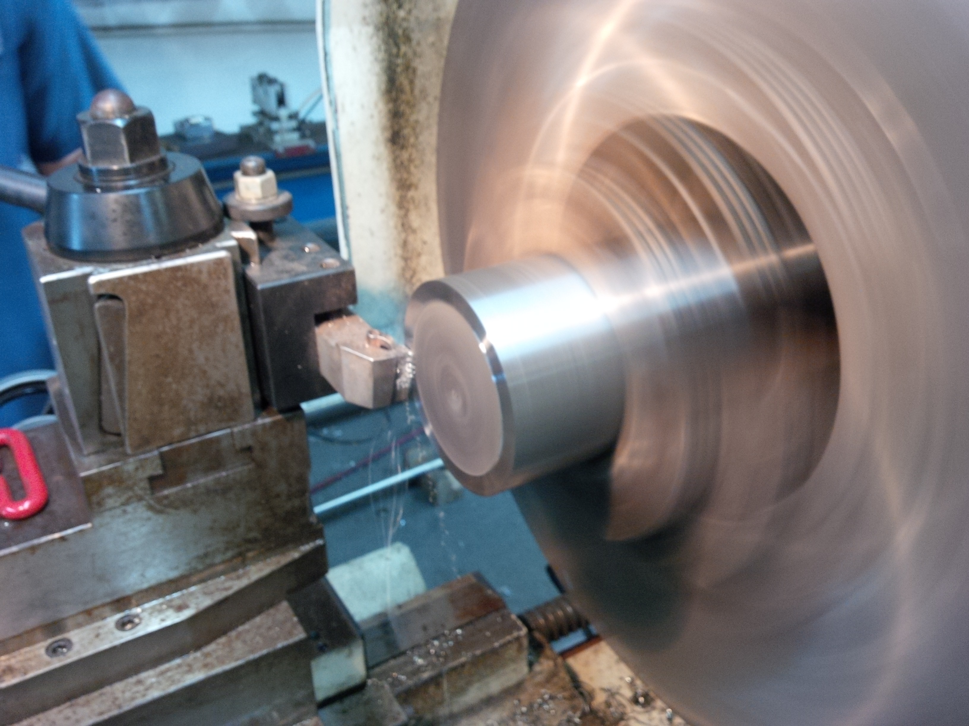
Machining new shaft in Straight Line Marine Shop
In order to fabricate the new shafts, we used Duplex 2250 stainless steel materials which are used extensively in applications that require good corrosion resistance and strength. More importantly, this material is certified for use in Lloyd’s classified vessels.
The purchased material was 5 inches in diameter but was sent to a centerless grinder to grind the material down to 125mm to match the old shafts. Centerless grinding is a machining process that uses abrasive cutting to remove material from the shaft. Centerless grinding differs from centered grinding operations in that no spindle or fixture is used to locate and secure the shaft which is secured between two rotary grinding wheels, and the speed of their rotation relative to each other determines the rate at which material is removed from the shaft. Other than this process, all other machining was performed in our shop at Straight Line Marine
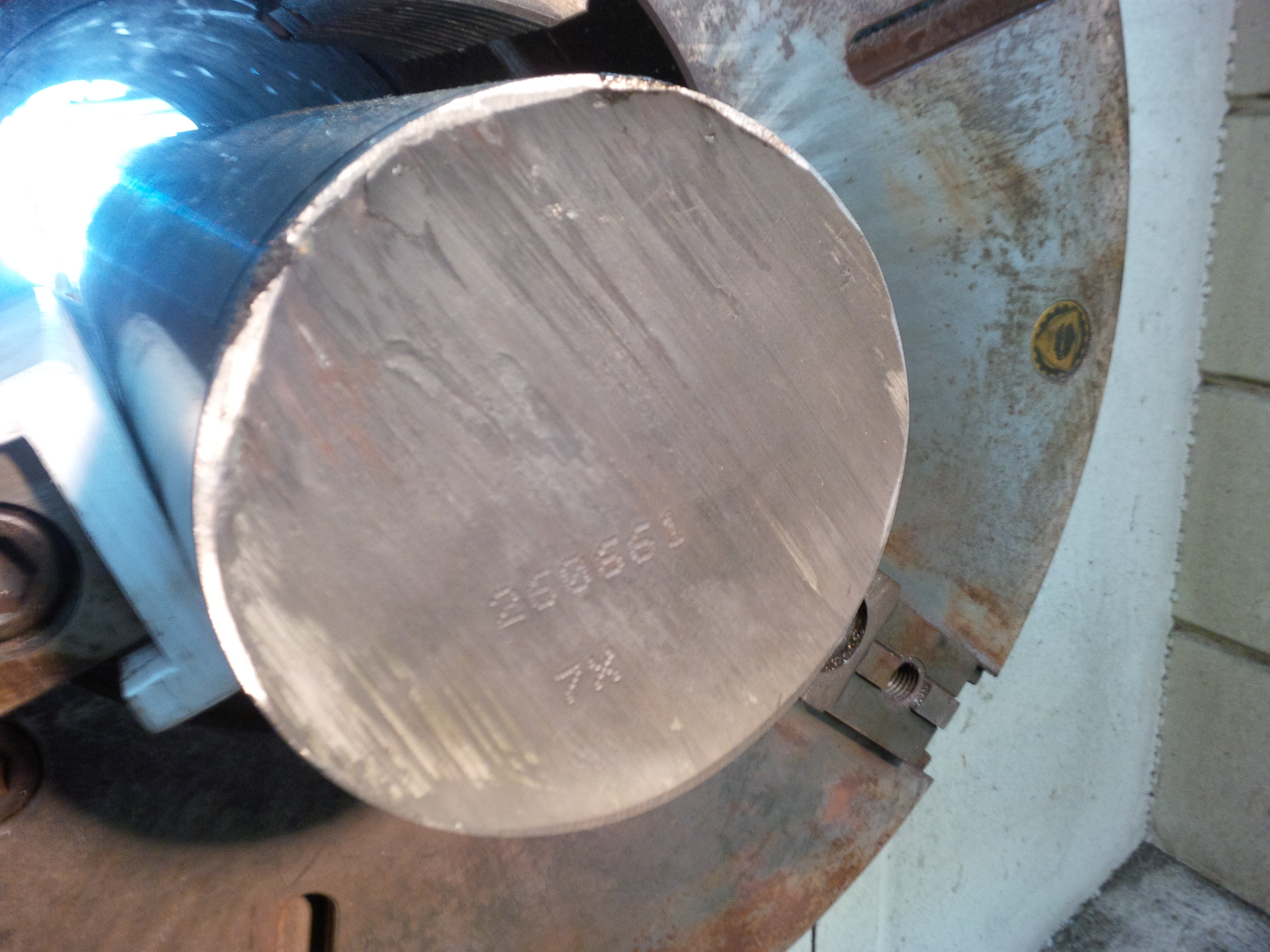
Lloyd’s requirement – “Heat” number applied to end of new shaft
Another part of the Lloyd’s process is tracing the “heat” number. This is a number that is stamped on the end of the shaft at the original foundry. The material gets a “Quality Assurance Certificate of Test” that outlines the materials metallurgical composition along with tensile and Rockwell strength measurements. Once the fabrication process was complete, the “heat” number is again stamped on the end of the cleanly machined new shaft. This is a requirement from Lloyd’s to enable them to track the material from foundry to vessel and ensure compliance.
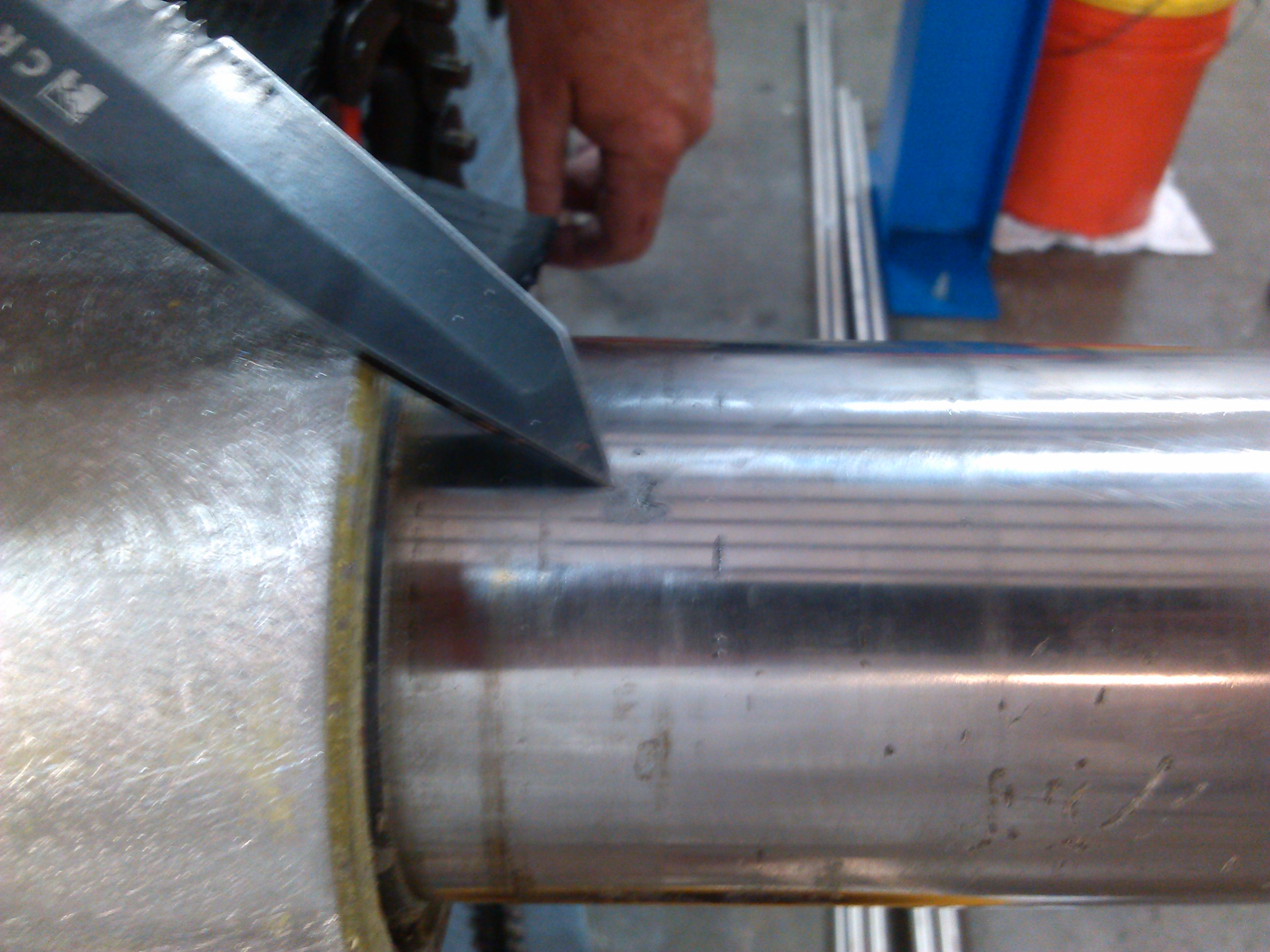
The final step in the process is to do a red dye penetrant crack test on the key ways and tapers. Red dye crack tests are used to detect casting, forging and welding surface defects such as hairline cracks, surface porosity, leaks in new products, and fatigue cracks on in-service components.
Lloyd’s requires that this process be completed by a Level II certified crack test technician. Our lead machinist, Chris Z. holds this designation and is qualified to perform the work.
When you required work on a Lloyd’s classified vessel, it is important to hire Lloyd’s certified technicians or risk losing the classification on the yacht and all the benefits that go with it.
Pitting on Shafts and Hydraulic Cylinders – when to repair or replace?
Hydraulic Cylinder Rebuild – Pitting on the Rod requires replacement
It is a fairly common occurrence for us to find pitting on hydraulic cylinders or shafts that we work on in our shop at Straight Line Marine. This is typically caused by corrosion from salt water, crevice corrosion or as a result of cheap stainless steel material used in fabrication. The lip seals on a shaft need a smooth surface or the hydraulic fluids will leak out causing a reduction in the performance of the units and, in this case, hydraulic fluid leaking into the ocean.
Crevice Corrosion on Shafts will Destroy a Lip Seal System
To fix this problem on large propeller shafts, we would perform a process called cladding in our machine shop. Cladding or shaft weld-over, is the process of repairing a worn or damaged area on a propeller shaft or rudder shaft. Stainless steel shafts can be damaged by excessive wear in contact areas, such as bearings or seals, due to long life or misalignment. Shafts can also be damaged from crevice corrosion or stray current corrosion. Straight Line Marine is the only shop in Florida that is ABS approved to perform this type of work. Replacing a large shaft could cost up to $25,000 each shaft, depending on the size. However, the cladding repair is only a few thousand dollars. For smaller shafts like sailboat shafts or hydraulic cylinder rods, we would simply buy new rod material and scrap out the old rods.
The convenience of having a machine shop (Straight Line Marine) and hydraulics shop (High Seas Hydraulics) under one roof ensures our customers that they can get the right level of expertise no matter how big or how small their needs.
Replacing a Seakeeper® Gyro Stabilizer – takes the right tools and the right know-how
A 65 meter (213 foot) Palmer Johnson yacht at the Lauderdale Marine Center needed to replace its Seakeeper Gyro Stabilizer. A Gyro Stabilizer is an alternative to a Fin Stabilizer, first used to control a ship’s roll in the late 1920s and early 1930s for warships and then passenger liners. Today, it is commonly used on all types of marine craft from luxury yachts to commercial vessels. The Gyro Stabilizer requires no through-hull cutting, eliminating the need for drag producing & damage-prone appendages.
High Seas Yacht Service was brought in to act as a “rigging company” to remove and replace the 2000 pound Seakeeper Gyro Stabilizer.
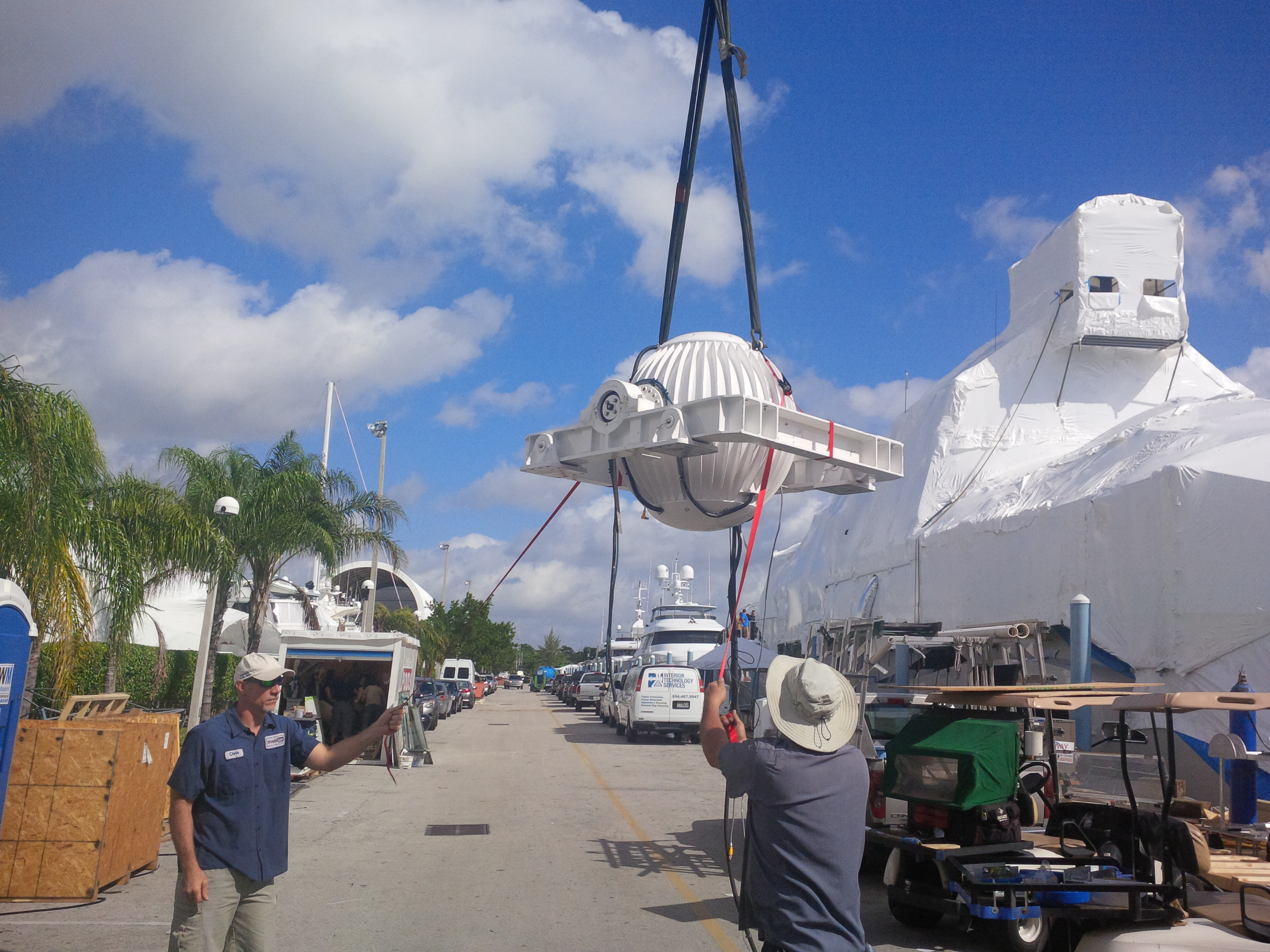
Seakeeper Gyro Stabilizer
We had to pick up Seakeeper Gyro Stabilizer in the engine room using up to seven different come-alongs (chain hoists) hanging from beam clamps on the engine room ceiling. We then had to swing it around the engines and run it through a small hatch in the engine room wall.
One of the challenges was the aluminum housing for the ball was not designed to take the 2000 lb. weight. So we had to pick it up and “monkey swing” it until we could lower it into a properly designed moving cradle.
Once we removed the original Seakeeper Gyro Stabilizer, we reversed the process to install a replacement unit.
The job took two days to complete, so the captain and crew could once again enjoy smooth sailing.
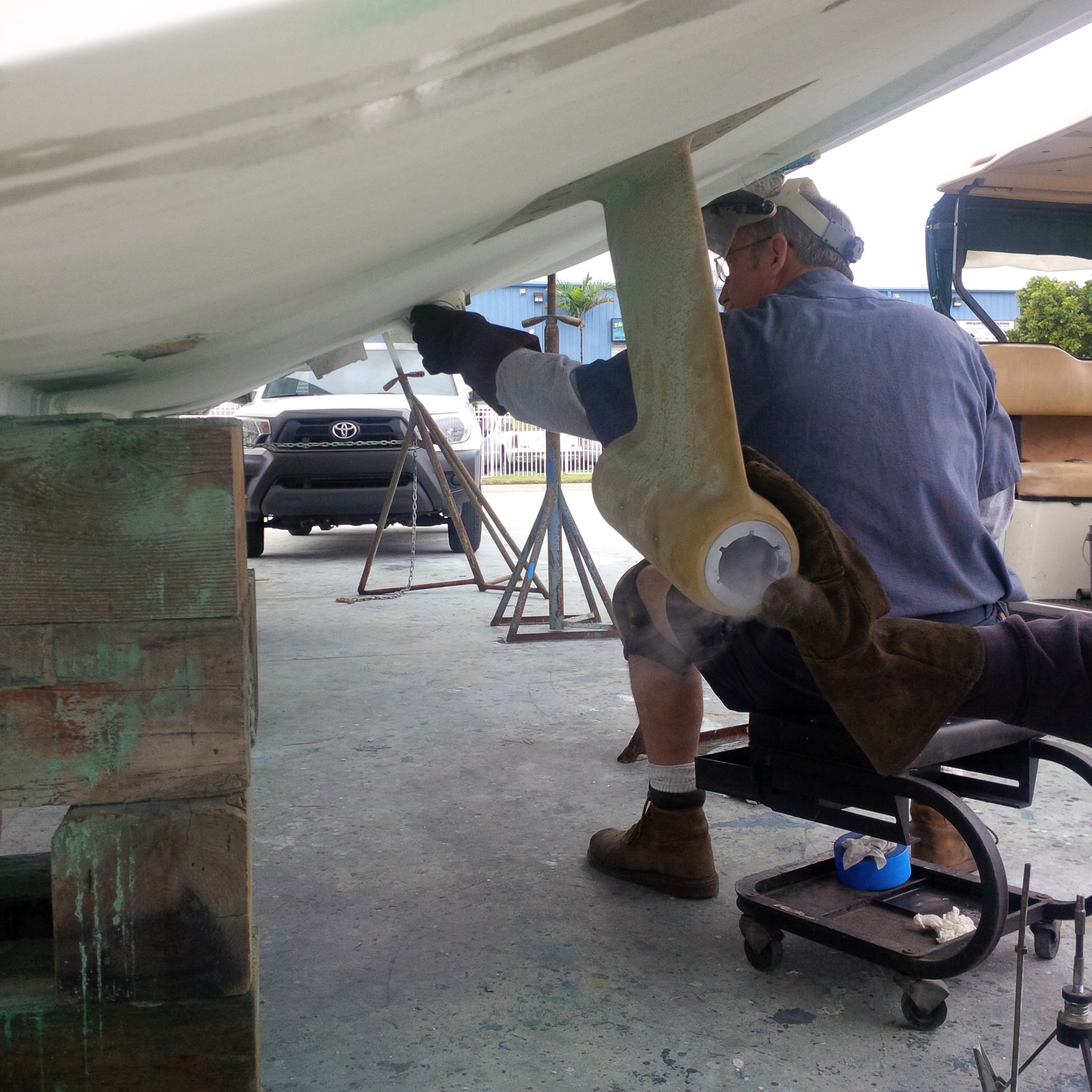
Strut Alignments – big or small, the process is the same
 We recently started work on a 120 foot Bennetti yacht re-aligning the struts and straightening the shafts. We have written about strut alignments in past articles – but these are the heaviest to date weighing in at 1400 lbs each.
Once the struts were removed and cleaned, the re-installation began with prepping the surface to remount 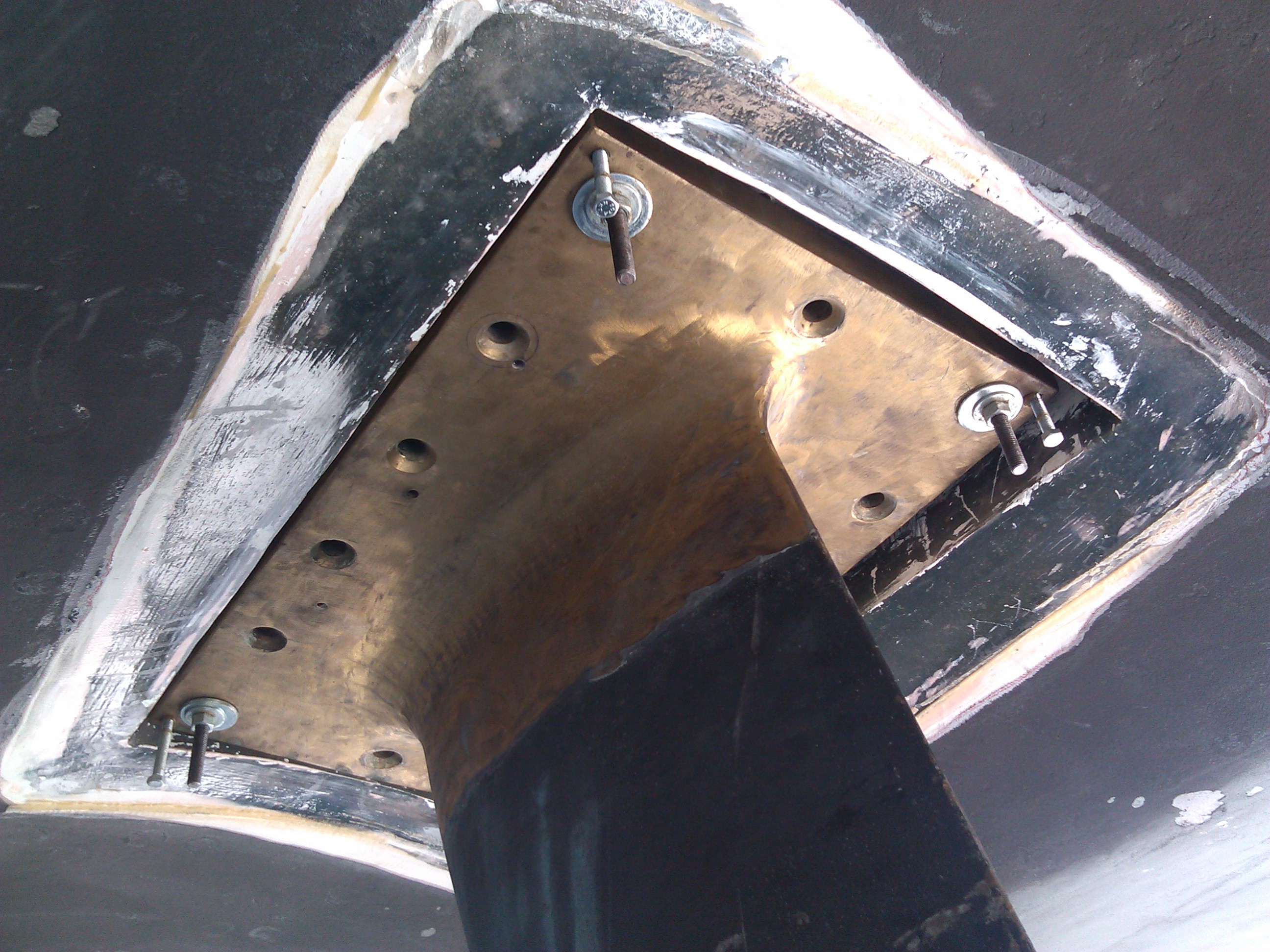 the struts. Once complete using the forklift and come-alongs the struts were put back into place. In order to ensure exact alignment, we used an optical scope. Optical Scope Alignments or “Scoping” for short; is the most advanced method for obtaining a perfect marine shaft alignment with struts, shaft logs, engines or v-drives. Scoping is the latest generation of alignment technology and far more advanced than the old piano wire system and even laser alignments.
 To finish the re-installation of the struts, we use CHOCKFAST® ORGANGE to fill the gaps between the strut installation and the hull of the boat. CHOCKFAST is an engineered epoxy chocking material that is used to cast-in-place permanent machinery supports for all sizes and types of main engines and marine auxiliary equipment. Because it conforms precisely to any surface profile, CHOCKFAST eliminates the machining of foundation and mounting surfaces as well as the fitting of the old-style steel chocks.
CHOCKFAST® Orange is a conveniently pourable, two-component, structural epoxy “chock” that replaces tediously fitted steel shims (or steel chocks) assuring exact contact with machined or un-machined equipment bedplates.
This is the only method to gain an accurate alignment without complicated line boring or other machining processes. All 1400 lbs were carefully adjusted to get the strut bearing within 0.005” of a perfect alignment.
Specialist or Generalist – Which to choose for running gear
Recently we encountered a common problem – a yacht owner had a vibration problem and went to one of the local boat yards for help. Most yards have good general marine service people that have a general but limited knowledge of many of the yacht systems. After all, a service yard cannot afford to staff their team with specialist in all systems. They did the normal things – sent the shafts out to a prop shop, changed cutlass bearings and did a routine engine alignment. Since the yard did not have a running gear specialist they missed a few subtle problems with strut alignments and engine mounts and did not fix the problem.

Optical Scope Alignment check for accuracy
The end result is a customer that is now in our yard and starting over with shafts out and a detailed alignment check. Unfortunately, this is repeating much of the work that the customer thought he was getting, and paid for, to begin with.
When I have an ache or pain I first go to my trusted Doctor, a general practitioner. He reviews my problem and then sends me to a specialist. He did his job and is done. It is now time for the specialist to do their job.
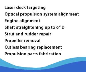
If you only want to have bearings replaced and the shaft sent to a prop shop then go to a general yard. If you have a vibration problem or want a detailed alignment check then make sure the yard you choose is prepared to perform a laser deck target (if needed), perform an optical scope alignment check of all struts and engines, knows your engine mounts in detail along with proper balancing techniques, knows the detailed points of coupling checks and the right procedures for a prop fit.
Thordon Shaft Bearings – Not Just for the Big Boats
Thordon Shaft Bearings
We are going through the running gear system on a 36 foot Glasstech built fishing boat – a classic looking walk around. The shafts are out for straightening and engine alignment to cure a persistent problem with a port side vibration. We are also replacing the shaft bearings.
The vessel was built with Thordon plastic shaft bearings. Thordon material is a hard compound that is an alternative to rubber cutless bearings. Thordon bearings are common in large commercial vessels (over 1,000 ton) and we see them in our yard on Trinity’s and other vessels from 120 foot and larger.
It is not so common to see Thordon’s in smaller vessels although they can be found in many Hatteras’. One advantage with Thordon bearings is the elimination of bearing squeal or, more technically, “stick-slip”. Bearing squeal is sometimes found with rubber bearings on stainless prop shafts when the shafts are turning extremely slowly. The shaft is not spinning fast enough to get the hydrodynamic lift of water between the rubber and the stainless steel. The result is a squealing sound. Not a big deal, unless you are in trolling mode or drifting, trying to catch fish.
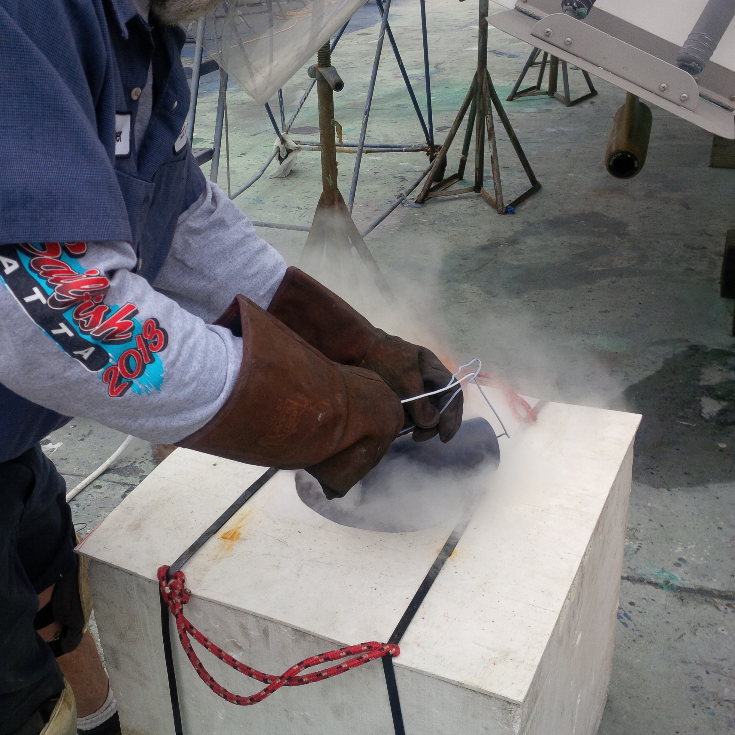
Liquid nitrogen process for Thordon Bearings
Thordon bearings are installed with an interference fit. The bearing OD is machined larger than the strut barrel and frozen down to shrink the OD for installation. We use liquid nitrogen (minus 270 degrees) to shrink the bearing. It only takes a few minutes in the liquid nitrogen to shrink and 15 to 30 seconds in the strut barrel to warm up and fit tight. You have to move fast to get it right the first time.
 Click to watch the video of a day at High Seas Yacht Service.
 Click to watch Marine Industries Association of South Florida video featuring Salty Jobs at High Seas Services.