

Replacement Inflatable Shaft Seal on a Kobelso Eagle System
We see all types of shaft seal systems working on various mega-yachts including this Kobelco Eagle product out of a 130′ Alloy. The vessel is in the yard for updating in many areas and we were given the opportunity to pull the shafts to check for engine and strut alignments.
The Kobelco Eagle shaft seal system includes an inflatable seal in the body. This seal operates similar to the emergency shaft seal bladder system found in Wartsila seals. The prior post also included a video showing how the system works.
If there is a need to change the shaft lip seal, or another emergency occurs, air is injected into the port and the rubber element acts like a bicycle tire inflating around the shaft and sealing off most of the water. The system is designed for emergencies only and the shaft cannot rotate while the seal is inflated.
In this picture you can see the old inflatable seal with a brass air tube removed from the seal housing. The replacement seal is already in place and the new tube is coming through the housing in the top of the picture.
Stay tuned for an updated post on the Kobelco-Eagle replacement lip seals.
A poorly machined coupler taper on a shaft will definitely lead to vibration problems.
We are working through a few issues with a customer that has had persistent vibration problems on his 80′ vessel. Once the shafts were out and in the machine shop we noticed an obvious problem with one of the coupler tapers. As the shaft was rotating in the shaft straightener, you could see that the fine line where the taper blends into the shaft had a visual wobble. This is a sign of a taper that was cut off-center. A few measurements confirmed that the center hole used to hold the shaft centered in the lathe for machining was off 0.020″.
That means the pilot on the coupler was running out 0.020″ (which was confirmed by putting the coupler back on the shaft) causing the shaft to run-out the same. In our business 0.020″ is a huge number that is definitely one source of running gear vibration.
The remedy was relatively simple – put the shaft in the lathe and recut the taper. We had to use the steady rest in the lathe since the center hole was useless. By recutting the taper the coupler will fit a bit further down the shaft which, in effect, shortens the shaft length. Fortunately we had a little length to play with so the only other change involved moving the Spurs line cutter holding block. I will put up a post on this topic later.
Once the taper was recut the coupler was lapped on (the same way the prop was lapped in my prior post) for a perfect fit. The coupler had to be refaced but amazingly the pilot ran-out 0.001″ without any additional machining. The coupler was manufactured true.
A short video will help understand visually what we saw. Please excuse our amateur video editing – this is work in process.
Stay tuned for more info on this job and a final sea-trial report.
When shafts are in the machine shop for checking, straightening or repairing you should have the props and couplers lapped onto the shaft. Lapping the bore of the prop/coupler to the shaft taper ensures a 90-100% fit between the surfaces. If you are installing new propellers or there has been damage, this process becomes even more important. It is not uncommon to find a prop or coupler bore that is only touching in certain high points on the taper. A poor fit can cause the prop to be slightly off balance on the shaft. A poor fit with low contact is also more likely to become a loose prop at some point in time.
Lapping is the process of using a gritty paste between the two surfaces to allow them to grind together for a perfect fit. We prefer to lap while the shaft is in the lathe in order to take advantage of the shaft spinning and the overhead hoist to hold the heavy props and couplers. The process can also be done by hand while the shaft is still in the boat – but that is hard work and is less effective.
A video is worth a thousand words – here are two difference angles showing a lapping in progress.
Please give us a call when you are in need of running gear or shaft repair. Don’t waste money by having a machine shop only complete part of the job. Ask for everything to be lap fit.
Another 50′ Tiara came to us with a vibration problem that was diagnosed as shaft whip. This particular model has too much distance between the strut bearing and the v-drive engine. This is exactly the same problem encountered and posted on another Tiara last year.
The solution is fairly simple – add another cutlass bearing to the stern tube. However, this can only be done if the latest alignment technology is used. Not all struts are aligned perfectly to the stern tube. You can get away with less-than-perfect strut alignments if there is no bearing in the tube and the engine is aligned properly. This is seen all the time when a shaft is not going through the center of the stern tube.
With the addition of a cutlass bearing, the alignment is critical. On this project we did find one of the struts to be out of alignment to the stern tube. Therefore the strut had to come down and be realigned properly. While the Optical Scope system was set up, both v-drive engines got a precision alignment.

Tiara with a Strut Removed
V-drive alignments can be very complex. With the output coupling under the engine, the adjustment to the engine mounts can be intuitively opposite. It is very easy to get confused and move further out of alignment. Fortunately the Optical Scope simplifies the process and gives absolute confirmation when the engine is aligned properly.
Of course, the project was not complete until the customary sea-trial. All was smooth and the customer was very happy.
The vessel is now for saleand the listing broker is promoting the difference between a High Seas “fixed” Tiara and others still on the market.
If you have a shaking Tiara please give us a call for a free inspection and quote.

PSS Seal Refreshed and Ready to go
PSS Seals are found on many of the pleasure yachts. The PSS Seal system is a “face” seal that relies on the pressure between a carbon face stationary to the stern tube and a stainless steel face on the ring installed on the shaft.
Maintenance on these seals is pretty straightforward. If the shaft is out we will usually reface the stainless steel ring in our machine shop. A smooth, flat face, free of debris, is required for a solid seal. The carbon face is inspected for chips or cracks. If cracked they must be replaced. Finally, we inspect the bellow hose for cracks or other signs of wear. The bellow hose acts as a compression spring to keep the carbon against the stainless steel. If the bellow hose is aging, it will lose the spring effect and not apply enough tension. This is sometimes noticed if the seal leaks when throttling up the engines. Depending on the engine mounts, the engine will shift forward under prop load which eases the pressure between the stainless steel and the carbon. If the bellows is not compensating then leaking will occur. PSS recommends replacing the bellow hose every seven years.
Finally, during installation the stainless steel ring is compressed a distance, per the PSS manual (it varies with shaft diameter). Notice in the picture the sharpie mark on the shaft showing the position of the ring in the neutral state prior to compressing the bellows.
PSS Seal are very effective and easy to maintain. Give us a call if you have any questions or concerns with your shaft seal system.

Wartsila Seal Bladder System Tested on Shaft
Many of the large “Class” vessels have seal systems such as Wartsila or Duramax that have an emergency inflatable bladder. The system is basically an inflatable bladder (like a bicycle tire tube but far more durable) that is housed just aft of the ships seal system. If there is damage to the seal, air pressure is applied from a ship’s compressor or simple bicycle pump to inflate the bladder. The air press causes the bladder to tighten around the shaft and slow the leak to a small drip. If the system is operating properly it should maintain air pressure for hours. However, the systems are not designed to withstand the friction of the shaft turning. Usually the vessel has a shaft brake system to allow movement with one engine without the “down” shaft from turning.
We have just completed a 5 year ABS inspection on the running gear on a 121′ Heesen. We removed the Wartsila seals and tested the inflatable bladder at the shop. The picture below shows the set-up on the shaft (145 mm shafts). The video above shows the inflation of the bladder using a simple bicycle pump. It is a good thing we tested the bladder. We found the fittings on one side to be loose and would not hold air pressure for more than a few seconds.
Confidence at sea comes from careful preparation and testing of all the ship’s systems.

Prop, Shaft and Rudders on a 61' Marlow
The new owner and new Captain on a beautiful 61′ Marlow came into the yard. The vessel had a major vibration that was most noticeable when driving from the lower wing station.
After removing props we went through our standard running gear inspection process – checking shaft run-outs, bearing clearance, seals and engine mounts. The running gear all checked out within spec so no need to pull shafts and create a big bill.
The rudders were extremely loose with up to 0.125″ of play and slop in the tiller arm pins. This was clearly a source of vibration with the prop wash rattling the rudders around.
Marlow’s were built using cutlass bearings as lower rudder bearings. We believe that allows too much play and premature wear. The lowers and uppers were replaced with Tides Marine UHMW bearings. The machine shop re-bushed the tiller arms and made new pins for the tie-bar. New Tides Lip seals and back together – all nice and tight. We only traveled a hundred yards in the New River before the Captain declared the problem solved. A month later he sent us the following update:
“Hi Chris, Thought you should know that the boat is running better then the day we bought her, thank you. Less noise etc. And we can actually run over 1400rpm with out breaking plates. ”
Next time you have a vibration, try to listen closely to your rudders. Don’t assume it is a shaft or alignment problem. And make sure you use a contractor that will take the time to inspect before tearing apart. We saved this owner a tremendous amount of money by recommending a “pass” on a full shaft job.

Wartsila EL Shaft Seal with Compression Tool
Wartsila Shaft Seals are often found on larger Class Yachts. The principal of the system is based on a face seal created by a phenolic ring riding on a graphite base. The phenolic ring does wear with time and use similar to a brake pad.
This seal is out of a 121′ Heesen that is going through a normal 5 year ABS inspection. The running gear is completely removed, cutlass bearings replaced, engine and strut alignment checked, shafts, props and couplers are checked in the machine shop. Finally, the shaft seal system is removed for inspection. This particular seal is the EL ManeBar model. All the components were checked against the manufacturer’s specifications and found to still be acceptable to reinstall in the vessel.Once the shafts are installed the system must be adjusted or compressed to tolerance in order to create a dry shaft seal system. I wrote about a tool for a different Wartsila Seal model a few months ago. Wartsila has designed their seals with a special installation tool in order to get an even and controlled compression. For the EL Shaft Seal the tool is comprised of threaded rod, a “hook block”, nuts and washers. Each vessel with Wartsila Shaft Seals should have the tool on board. Unfortunately, since the tool is only used once every few (or five) years it is often hard to find. In this case, our machine shop fabricate this tool with Wartsila’s support and permission. A special thanks to Steve and Brian at Wartsila for their excellent customer support.

Creative PhotoShop work on a Classic Rybovich
You may have already seen this picture in circulation and we need to clear the air. This was a little humor along with some creative work on Photoshop.
This 1974 Classic 75′ Rybovich Motoryacht (one-of-a-kind) is meticulously maintained by her owner and is very “original”. During a recent haul-out for repower and transmission work we re-aligned the struts and will finish the engine alignment when everything is done in the engine room.
Thanks for all the “kind” words of encouragement from those that thought we suggested destroying a Classic. Also, I do not plan on engaging in a debate on the merits of Mercury vs. Yamaha in this application.

- Float aligning a cutlass bearing in a strut
In past posts we sea-trialed a 120′ Intermarine and observed a bad vibration with the vibration analysis expert and took a video of the obvious problem as seen on an aft cockpit table.

- Damming a float aligned cutlass bearing in preparation for injection
Once the bearing is set in place the ends need to be dammed with material in preparation for the Chockfast injection. Chockfast will fill the void around the bearing for a permanent set. A properly aligned cutlass bearing should be set for the life of the vessel if you keep it off the bottom.
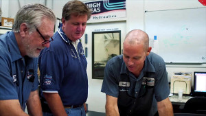 Click to watch the video of a day at High Seas Yacht Service.
 Click to watch Marine Industries Association of South Florida video featuring Salty Jobs at High Seas Services.